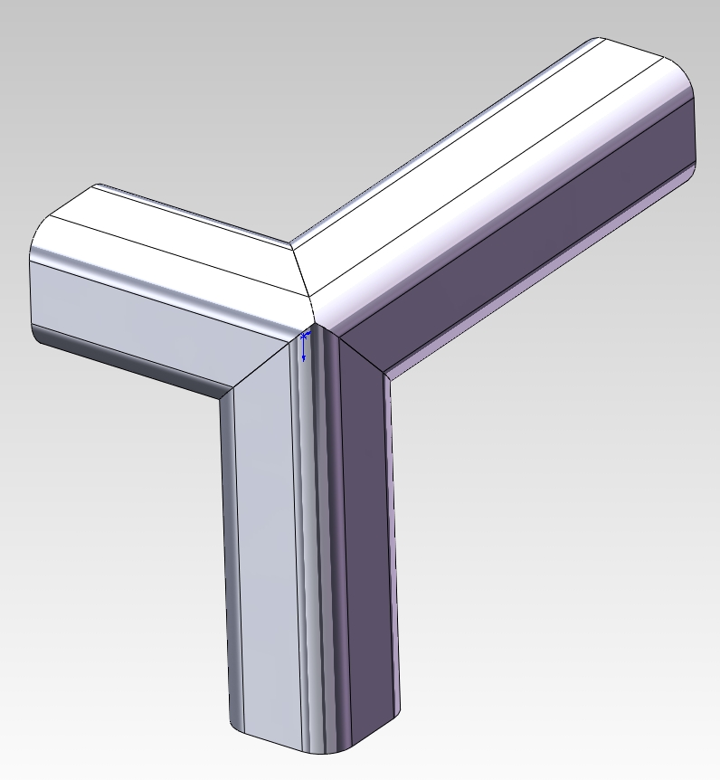
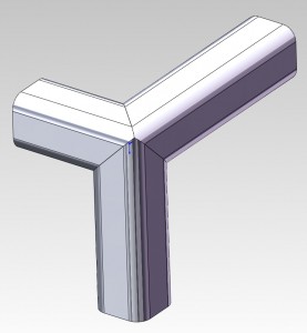
 I had an inquiry this morning regarding the Certified SolidWorks Professional (CSWP) exam for Weldments. The question was, “Am working thru the practice exam and cannot get the 3 miter corner to come out. Any hints on how you did it?” I went digging to find the files I used for the practice exam and found the original model with a nice 3 member miter in it. After playing with it for a few minutes I finally rediscovered how it works. The solution is not obvious so here is the trick to pulling it off.
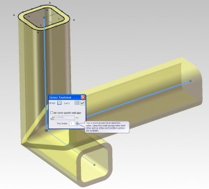
First, the 3 members must be made using one “Structural Member” feature in SolidWorks. This means that you cannot use any weldment profiles that have undercut features such as the 80/20 profiles that I have posted here. Build your structure using multiple Groups (SolidWorks will not allow 3 members in one Group to meet at a corner so you will need at least 2 Groups). While still editing the “Structural Member”, click the magic pink dot that represents the intersection of the 3 members in question. This brings up the Corner Treatment override tool. This is where the secret lies!
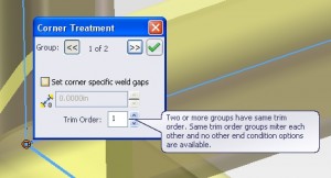
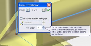
Clicking through the >> and << arrows, you can see all of the corner treatments that will be applied at this intersection. Notice the Trim Order box changes from 1 to 2, etc. as you click through the choices. The secret is to change the Trim Order for both intersections to the same number.
Notice the revealing message that pops up when you do this, “Two or more groups have the same trim order. Same trim order groups miter each other and no other end condition options are available.” The big hint is to make them the same and then they will all miter each other. For more details, you can also search the SolidWorks Help for “Weldments – Change Corner Treatment”.
Here is a sample SolidWorks file (in SW 2011 format). 3CornerMiterExample

