I’m going SolidWorks World next week and I’ve been told that the CSWP event on Monday night should be a good time. I remember seeing details about last year’s event where everyone got to play with the iCoaster. It looked cool. This year everyone gets to test drive an RC car. I’m not very good with RC cars, but there’s a design contest too. That’s something I can do.
The Problem: design a new wheel in SolidWorks for the SC10 RC car.
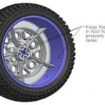
The Rules: Points will be awarded in these key areas: 1) Is the wheel designed and supplied in SolidWorks format? 2) Is the wheel rendered and/or animated in a cool way? 3) Is the wheel construction feasible? (decided by Team Associated engineers/designers)
The rules seem a bit awkward to me – the company obviously wants some free design work, but I want to have some fun. My best designs come when I ignore the Rules and just get creative (notice I said “ignore” and not “forget” – eventually you need to come back to the rules, but if you can ignore them for awhile, your creativity will not be limited.)

The first idea that comes to mind is an old toy – the Spirograph. What if my RC car wheel had spokes that looped around in a continuous weave that looked like one of those designs you can make with a Spirograph?
There must be a mathematical equation to describe the path made when a point on one circle is plotted as it rotates around another circle. If I can plot the path mathematically, maybe I can create a 3D path in SolidWorks to describe a sweep for the spokes of my wheel. After searching for “spirograph equation”, I discovered David Little’s page at Penn State University. As it turns out, the path of a Spirograph is called an epicycloid. It’s described by a pair of equations:
x(t)=(R+r)cos(t) + p*cos((R+r)t/r)

y(t)=(R+r)sin(t) + p*sin((R+r)t/r)
R and r are the radii of the 2 circles, p is the position along the radius of the first circle (the hole you put your pencil in on a Spirograph). Mr Little’s website has a cool Java applet that draws epicycloids based upon your input. If you experiment with this tool, you can discover all sorts of interesting geometry. After a few iterations, I found a combination that I thought might look like the spokes of a wheel using the values R=72, r=66 and p=67.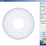
Where would engineers be without the spreadsheet? I remember seeing a documentary on PBS called Nerds where I learned that the first spreadsheet was called Visicalc and it was for accountants. Excel is the tool that I am most familiar with – version 2003 being most preferred. The Excel version of these formulas seems a bit more complicated. First, cells are made for all of the constants (R, r, p). I added a few extra for scaling – the final goal is an equation of a curve that will intersect the hub and rim of our wheel. Examination of the formula quickly reveals that t is an angular variable. I made a column for t in degrees because I know this is a cyclical function that will repeat every 360º (remember, it’s a circle rotating around a circle). I also made a column for radians (degrees times pi divided by 180) because Excel evaluates sine and cosine in radians. I probably could change this default somewhere, but that is something I would probably forget later and it’s easy to remember how to convert degrees to radians.
I know I want X and Y coordinates for the entire path and that they will eventually return to zero. I wasn’t sure how to know how many points to plot so I made some check formulas that subtract the current X and Y values from the original X and Y values – when the check columns both hit zero, I know I’ve returned home. The last step for X and Y is to plot a curve using Excel’s graph tool. The Excel graph matches the epicycloid plot so I know I’m on the right track. (Actually, I’m thoroughly appreciating the same feature that the original users of Visicalc appreciated, Excel’s power to iterate until I get it right.)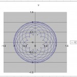
Some interesting observations: my epicycloid has 12 loops and the equation to describe it requires 3960 points at one degree increments. If I made another with 22 loops, I would expect it to take 7560 points to describe it (360 x 21). For some reason, my check equations did not exactly return to zero until I placed a round function into my formulas – I added a variable for the number of rounded decimal places as well.
What about Z? The equations for an epicycloid are only in 2 dimensions, but I want a 3D path for my wheel spokes. The options are limitless, but a sine function would make a nice smooth equation and it would behave in a similar way as the epicycloid equations. Some constants are necessary to vary how often the equation returns to zero and vary its scale. Graphing the function over the same range gives a clue how the path will vary in Z.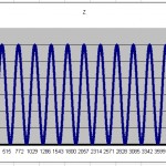
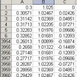 Excel’s worksheet functionality makes it easy to create formatted output. It turns out that the way the wheel was originally created, I need my X and Z data points to be swapped. By creating a new worksheet with only X, Y and Z values, I can swap the values very easily. The final result is a text file with 3960 points of X, Y and Z data.
Now to SolidWorks! The Insert Curve Through XYZ Points tool quickly creates a 3D path.
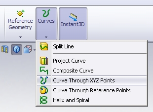 As a point of interest, I believe it was because of this tool that Walt Disney Imagineering chose SolidWorks as it’s 3D design tool – they had 3D points to describe the path of a rollercoaster and needed a tool to model the track. I created a second sketch on a principal plane perpendicular to the path. I started with just a sketch point and some dimensions tieing it down to the path.
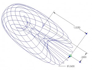 Then I made the geometry for my sweep all tied to the sketch point. This way, if I want to change the profile from a circle to a square, I don’t lose my dimensions when I delete the circle. The Sweep tool turns all this hard work into an effortless expression of mathematical beauty. A few features to tie the spokes to the wheel and I have my entry.
Of course, I must return to the rules. I already know I will not win because, although my design is interesting, it cannot be molded which is the intent of rule 3. Rule 1 is easy – SolidWorks makes the whole thing possible. So Rule 2 is the only one left to satisfy.
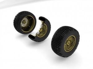 I’m running out of time so a quick assembly with a cut-away view and a few minutes of rendering in PhotoView 360 and, at last, I have an entry.
Here are all of the files I used to create this design. -Amos
AEA Entry 1 of 2
AEA Entry 2 of 2
Followup: SolidWorks World was great. The CSWP event was very fun even though I am a very poor RC driver.  I did not win the design contest (for obvious reasons). I did, however, win one of 40 SC-10 RC cars, which is VERY cool!
