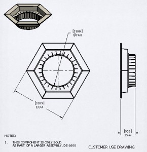
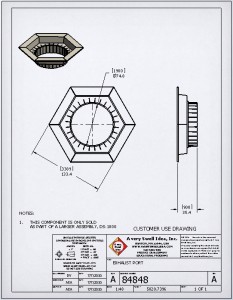
 It happens at every manufacturing facility I’ve come across. A customer or potential customer calls up and wants an engineering drawing of some part of a larger assembly so they can design their equipment to interface with it. The general assembly drawing you’ve created specifically for customers isn’t detailed enough. The catalog only shows a picture of the part in question. Their application is something you’ve never encountered before (if they will even describe it to you) and now you’ve got a decision to make.
Company policy states, “Thou shalt not send proprietary engineering data to anyone outside the company.” This is, of course, for good reason as your engineering design data is what differentiates you from every other competitor, it’s who you are, it’s your life blood and deserves protection at all costs (within reason). Enforce the policy and you upset the customer or worse yet, lose the sale. Send them the production drawing and you slowly erode the value of your intellectual property and run the risk of your competitor or customer stealing your design. Non Disclosure Agreements (NDA’s) can help, but they are a pain because you have to get lawyers involved and they’re difficult to manage. Some customers just will not sign them – what can you do?
The solution: Customer Use Drawings. Customer Use (CU) drawings are just what they sound like, a drawing made for a customer to use. They are different from production drawings that contain every detail needed to manufacture something. The information they offer is sufficient for the customer to make proper use of your product in their application. The level of detail will vary widely, but you can always expect a CU drawing to have less detail than a production drawing.
Companies handle CU drawings in different ways. Some will assign a completely different drawing number to a drawing that is designated for customer use. This can be challenging if you do not have an efficient way to link CU numbers to production numbers. Initial drawing creation is fairly simple as you can just take the production drawing and do a Save As to the new number. Then add, delete or change the drawing for customer use and you’re done. As you can see, one major limitation of this method is that now the production drawing and the CU drawing are no longer linked to each other. They might be driven by the same part or assembly so major design changes will carry through, but they will now have independent revision histories. The engineer/designer assigned to make changes at some future date needs to be careful to update both drawings separately. This doesn’t always ever happen.
Another method for creating CU drawings is to use the same drawing file for both. With this method, everything comes from one file so updates are simple. New drawing numbers do not need to be created and managed, making the search for the CU drawing the same as the search for the production version. Drawing creation is even easier than a Save As because you don’t need to delete anything. The only drawback that I can see is that if you revise a production part from A to B and change a feature that doesn’t show up on the CU drawing, you may still want to output a revised CU drawing to be consistent. I recommend hiding the revision history on a CU drawing so this change may be nothing more than renaming the file (if you have the revision level  in the filename). Having a different drawing number for the CU drawing enables independent revision histories. Most cases for the application of CU drawings, however, involve special one-time circumstances where a customer is asking for something out of the ordinary like the dimensions of the “small thermal exhaust port right below the main port”. A typical configuration drawing of the entire assembly would never include such inconsequential dimensions as no customer would need them (except yours). A CU drawing could be quickly made of just the “exhaust port” so the customer could be sure their “product” will fit inside. These cases are usually one-time requests that vary from customer to customer making separate revision histories unnecessary.
The tool that makes it possible to create production drawings and CU drawings from the same file is Layers. If you have a 2D CAD background like I do, you have probably worked with layers before. At WDI, like most firms that design products that fit inside buildings, we would design an entire themed attraction in one 2D drawing file using a different layer for every discipline. Each drawing sheet would have only certain layers showing and all the others hidden. In the 3D realm, this seems foreign to some, but the old rules still apply and layers make CU drawings possible.
![]()
In SolidWorks, the first thing you might consider is to turn on the Layer toolbar.
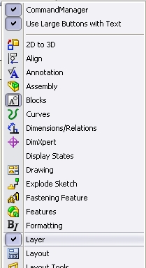
This gives you easy access to all of the layers and the button that brings up the Layers dialog box. Things you can control with the Layers dialog box include layer name and description, layer visibility (on/off), object color, object linetype style and object linetype thickness.
By default, SolidWorks places all objects on a special layer called –None-. This layer is special because it doesn’t really exist. It cannot be turned off nor changed. I mention it as if it were a real layer because it can be selected from the Layer toolbar when you are choosing what layer to place an object on. Placing an object on the –None- layer makes it always visible.
I created a few standard layers in my drawing templates. First, a layer called NOSHOW which is a dumping ground for important information that may be needed to make a drawing but you don’t want to show when creating output. Currently on the NOSHOW layer are dimensions used to define the titleblock. SolidWorks lets you hide things at will but it’s not always easy to unhide them if you do not know they are there. The NOSHOW layer makes it easy to see what’s there but meant not to be shown.
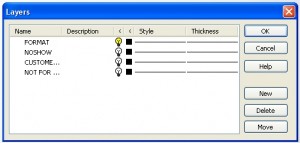 In addition, a layer called FORMAT where I put the drawing format (titleblock, border, etc.) enables me to turn off the sheet format when I want to print a copy of the drawing with just the drawing views and no titleblock. Having a titleblock implies officiality, completeness, design verification, drawing checks and approvals, assigned part numbers, etc. No titleblock implies a quick sketch, a negotiable design, a work in progress, not complete nor official, open to discussion, etc. There is a time and a place for both making the FORMAT layer a valuable tool.
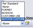 The other two layers I created are CUSTOMER USE and NOT FOR CUSTOMER. Placing data on these layers and turning the appropriate layer on or off makes creating CU drawings a reality. To create a CU drawing from a production drawing, simply select the items that are not for customer (CTRL-Click to select multiple items) and place them on the NOT FOR CUSTOMER layer by selecting the layer in the toolbar. Turn off that layer by launching the Layers dialog box and clicking the light bulb icon beside it and click OK. Change your current layer from -None- to CUSTOMER USE by selecting it from the pop-up list in the toolbar. Add any details that are customer specific including a note that says CUSTOMER USE DRAWING. Any items left on the –None- layer will show up on both the CU drawing and the production drawing.
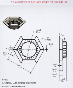
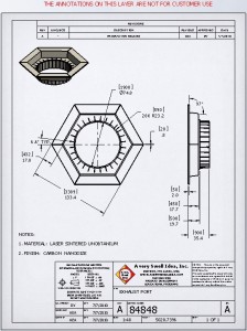
By hiding the CUSTOMER USE layer and showing the NOT FOR CUSTOMER layer, you can see what the production drawing will look like. I usually place some text on the NOT FOR CUSTOMER layer somewhere outside the printable area that says, “THE ANNOTATIONS ON THIS LAYER ARE NOT FOR CUSTOMER USE”. This helps the user to know what layers are turned on or off.
The final step is output. It is always a good practice to save engineering documentation in a neutral file format, preferably one that is difficult to edit. Many companies use PDF files for their released documents. The Save As tool in SolidWorks includes a PDF option, making creating PDF’s easy. I typically recommend using a filename that captures the moment in time for the file. For example, a drawing 84848.slddrw could be saved as 84848.pdf but the next time it is revised, a new PDF would overwrite the old. How would you know what version of the file you had? Saving it as 84848 Rev A.pdf creates a snapshot in time at Rev A for this drawing. A revised drawing would become 84848 Rev B.pdf thus preserving the older version. If your revision system doesn’t include revision tracking, you might use the date instead, as in 84848 07Jul10.pdf. For a Customer Use drawing, I recommend app ending CU to the end of the filename so they sort next to each other in your file system (e.g. 84848 Rev A CU.pdf). Adding “CU” to the end makes it clear what the file is intended for.
My drawing templates are setup to include both the CUSTOMER USE and the NOT FOR CUSTOMER layers but they are both turned off. All drawing is done on the –None- layer. The CU features lie dormant until I get that call for some obscure question about the size of my exhaust port compared to the size of a womp rat. Since I’ve never seen a womp rat and I’m not sure what the customer really needs, I send them a CU drawing of the exhaust port and everybody is happy (for now).
For your convenience I’ve created a detailed printable tutorial that you can download here: AVSITUT-0017 CustomerUseDrawings Rev B.
SolidWorks 2010 files for this tutorial can be downloaded here: CustomerUseDrawings.
Update: Special thanks to GabiJack.com for the idea of placing a downloadable pdf tutorial at the end of this post. Her tutorial on Modeling a pair of scissors is an excellent example.
